
Blog
What Is a Powder Pulverizer and How Does It Work?
A Powder Pulverizer is industrial equipment designed to reduce solid materials into controlled, fine particles. It is used in food processing, minerals, chemicals, pharmaceuticals, plastics, and other manufacturing fields. The machine may look simple from the outside. Inside, however, several forces work together.
Most models use impact, compression, shear, or a combination of these forces. A rotating hammer can strike a hard feed material repeatedly. Grinding rollers can press particles between moving surfaces. Airflow may then carry lighter particles toward a classifier. Larger particles return for further grinding. Fine particles leave through a collection system.
Particle size is not controlled by grinding force alone. Rotor speed, screen openings, feed rate, material hardness, and moisture all influence the final result. A damp material may form clumps and reduce output. Excessive speed can increase heat, noise, and equipment wear. These details matter during real production.
Operators usually inspect vibration, bearing temperature, dust seals, and product consistency. They also check whether the feed enters evenly. A blocked screen can change performance within minutes. That assumption can fail.
Reliable pulverizing requires more than choosing a powerful motor. Equipment selection should match the material, target fineness, capacity, and safety requirements. This guide explains how a Powder Pulverizer works, what happens inside its grinding chamber, and which operating factors affect efficiency. It also considers practical limitations, because diagrams often make the process look cleaner than it really is. Careful testing remains essential.
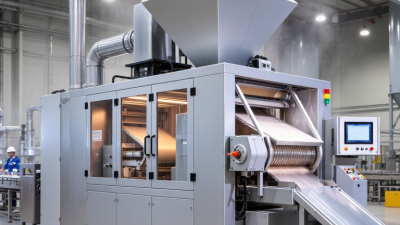
Powder Pulverizer Basics: Reducing 10 mm Feedstock to 10–100 μm Particles
What Is a Powder Pulverizer and How Does It Work?
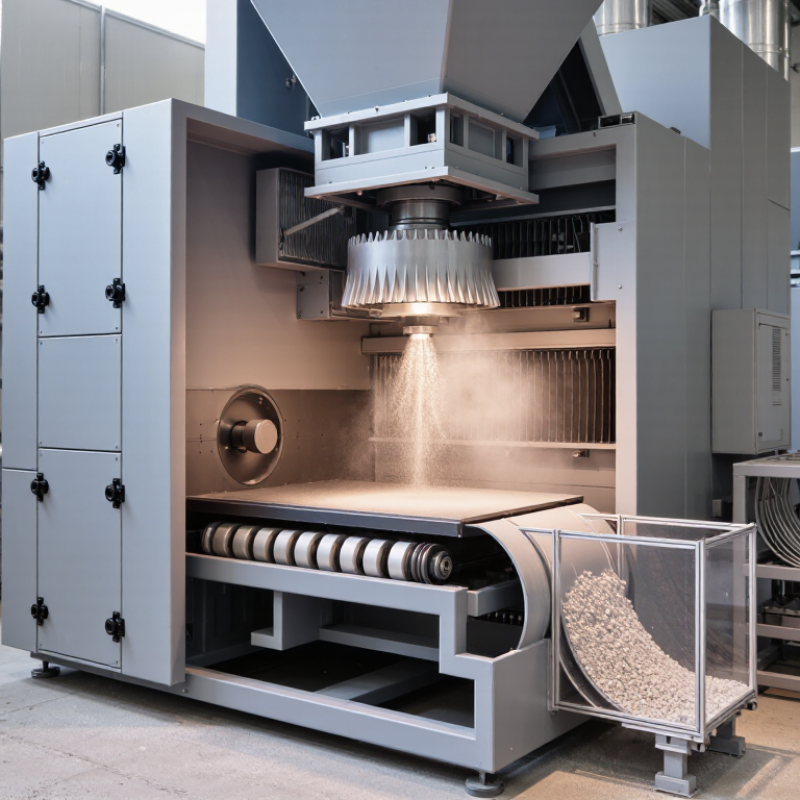
A powder pulverizer converts coarse feedstock into controlled fine particles. A 10 mm piece must become 10–100 μm material. That means a 100–1,000-fold reduction in particle diameter. Its volume reduction can reach one million to one billion times, depending on shape. The process usually combines impact, compression, and shear. Rotating hammers or pins break the feed, while airflow carries smaller particles forward. A classifier rejects oversized particles for another pass. The target is rarely achieved in one step.
Feed condition strongly affects performance. Moist material may smear instead of fracture. Hard particles can increase heat, vibration, and energy demand. The International Energy Agency’s Energy Efficiency 2023 report estimates that industry consumes about 37% of global final energy. Efficient size reduction therefore matters beyond production speed. Operators should monitor feed moisture, motor load, outlet temperature, and particle distribution. Small details matter.
Particle size should be verified, not guessed from appearance. ISO 13320:2020 describes laser diffraction methods for measuring particle-size distributions. ASTM E11 provides specifications for test sieves, although very fine particles may require optical analysis. A 10–100 μm result is also a distribution, not one perfect size. For example, a batch may contain 65 μm particles alongside unwanted 180 μm fragments. That indicates classification or recirculation problems. Pulverizers can be powerful, but “finer” does not automatically mean better.
Core Components: 1,000–10,000 rpm Rotors, Screens, Classifiers, and Cyclones
What Is a Powder Pulverizer and How Does It Work?
A powder pulverizer reduces solid materials through impact, shear, and controlled airflow. Its rotor is the working heart of the machine. Depending on the material, the rotor may turn between 1,000 and 10,000 rpm. Lower speeds limit heat and wear. Higher speeds create stronger size reduction. Too much speed can damage sensitive materials.
Inside the grinding chamber, screens control the particles leaving the rotor zone. A smaller screen usually produces finer powder, but it can restrict airflow. Classifiers add another layer of control. They separate particles by size and density, sending coarse material back for further grinding. This loop improves consistency. It also increases energy use. That trade-off deserves attention.
Cyclones then separate powder from the moving air. Their curved chamber forces heavier particles toward the walls, where they fall into a collection container. Operators should check pressure, vibration, bearing temperature, and particle size during production. A sieve test can confirm whether the screen and classifier settings perform as expected. Small air leaks matter. They can reduce collection efficiency and spread dust around the equipment. In practice, moisture often causes more trouble than expected. Damp material may clog screens, overload the rotor, and create uneven powder. The process looks simple, but stable results require careful adjustment.
Grinding Mechanisms: Combining Impact, Shear, Compression, and Airflow
A powder pulverizer reduces solid material into controlled particle sizes through several forces working together. Its performance depends on the material’s hardness, moisture, feed rate, and target fineness. In practical operation, operators inspect the feed and adjust settings gradually rather than relying on one fixed recipe.
Impact delivers the initial breakage. Fast-moving hammers, pins, or particles strike the feed and fracture larger pieces.
Shear then cuts or tears material along weak planes, which helps produce a more uniform powder.
Compression adds pressure between surfaces, especially when the feed contains dense or brittle particles. These mechanisms overlap inside the grinding chamber.
Airflow controls movement as much as it supports grinding. A moving air stream carries fine particles away while heavier particles remain longer for additional treatment. This separation can reduce unnecessary grinding and limit heat buildup. However, excessive airflow may remove particles too early, while weak airflow can cause accumulation and uneven discharge. The balance is not always obvious. Real-world testing matters.
Experienced technicians monitor vibration, temperature, sound, and particle-size samples during production. A sudden rise in temperature may indicate overloading, poor ventilation, or unsuitable moisture levels. Cleaning and inspection also protect consistency, because residue can change the next batch’s behavior. Even well-designed equipment has limits. A setting that works for a dry, brittle feed may perform poorly with a tough or slightly damp material. Careful adjustment remains essential.
Operating Sequence: Feeding, Pulverizing, Classification, and Discharge
What Is a Powder Pulverizer and How Does It Work?
A powder pulverizer reduces solid materials into controlled, fine particles. Its operating sequence begins with feeding. Operators introduce material through a measured inlet. A steady feed rate prevents sudden pressure changes and uneven grinding. Inside the chamber, rotating tools, impact surfaces, or air forces break the particles apart. The exact result depends on material hardness, moisture, and machine settings.
Pulverizing is only one stage. Airflow carries lighter particles toward the classification area. A classifier separates particles by size and density. Oversized particles return to the grinding zone for further reduction. Acceptable particles move toward the outlet. During discharge, the finished powder leaves through a sealed path or collection system. In practice, the sequence is rarely perfectly smooth. Moist material may build up. An inexperienced operator may also adjust speed too quickly. Careful observation matters.
Tips: Check feed consistency before increasing speed. Watch vibration, temperature, and airflow during operation. Clean contact surfaces regularly, but follow the equipment manual. Small changes can affect particle size. Record each adjustment. This makes later troubleshooting more reliable. Personally, I would not judge performance from appearance alone. A powder can look uniform while its particle distribution remains inconsistent. Sampling and simple testing provide stronger evidence.
Powder Pulverizer Operating Sequence
The chart shows a representative reduction in median particle size through the four main operating stages. Feed material enters at a coarse size, is reduced by mechanical impact and shear during pulverizing, and is then screened or air-classified before the acceptable powder is discharged. Actual values vary with material properties, moisture, rotor speed, screen size, and classifier settings.
Performance and Safety: 1–100 μm Output, 5–500 kg/h, and Dust Control
A powder pulverizer reduces solid material into fine particles through impact, compression, or shear. Its working principle is simple. Material enters a grinding chamber through a controlled feeder. Rotating hammers, pins, or discs break the particles against a lined surface. Airflow then carries the ground powder toward a classifier or collection filter. The final size depends on rotor speed, screen openings, feed rate, and material hardness.
A properly selected machine can produce particles from 1 to 100 μm. Throughput may range from 5 to 500 kg/h, but feed properties change the result. Hard, damp, or sticky material usually lowers capacity. In practical testing, operators should measure particle size at several output points, not only at startup. That estimate is not universal. Real plants often discover that moisture changes performance more than expected. Small adjustments to feed rate can prevent unstable operation.
Dust control is essential during feeding, grinding, and discharge. Enclosed transfer lines, local extraction, sealed bearings, and suitable filtration help limit airborne powder. Operators should inspect gaskets and filters before each production shift. Good ventilation alone may not control fine dust near a discharge point. Grounded equipment and static-control procedures also reduce ignition risks where combustible powders are present. Personal protective equipment remains necessary, even when the system appears sealed. A clean machine is safer, but cleaning methods must avoid sending dust back into the room.
What Is a Powder Pulverizer and How Does It Work? — Performance and Safety: 1–100 μm Output, 5–500 kg/h, and Dust Control
| Performance or Safety Dimension | Typical Range or Value | How It Works or What It Means | Operating and Design Considerations |
|---|---|---|---|
| Definition | Mechanical size-reduction equipment | A powder pulverizer breaks solid feed material into smaller particles by impact, compression, attrition, or a combination of these forces. | The machine should be selected according to the material’s hardness, moisture, abrasiveness, temperature sensitivity, and dust behavior. |
| Common Output Particle Size | 1–100 μm | Fine pulverizers, pin mills, air-classifying mills, and jet mills can produce powder in this range when feed conditions and classification are properly controlled. | Actual particle-size distribution depends on rotor speed, grinding gap, air flow, feed rate, material properties, and the selected classifier. |
| Typical Throughput | 5–500 kg/h | Small laboratory and pilot units generally operate at the lower end, while larger production units can process several hundred kilograms per hour. | Capacity is not fixed. Fine targets, hard materials, high moisture, and narrow particle-size specifications usually reduce throughput. |
| Feed Particle Size | Usually below 5–10 mm | Many fine pulverizers require pre-crushed or screened feed so that the grinding chamber can operate efficiently. | Oversized feed can cause blockages, excessive vibration, uneven wear, and motor overload. A suitable upstream crusher or screen may be required. |
| Main Size-Reduction Mechanisms | Impact, attrition, compression, and shear | High-speed pins, hammers, discs, rollers, or fluid jets transfer energy to the particles and reduce their size. | The mechanism must match the product. Heat-sensitive powders may require air cooling, while abrasive products may require wear-resistant contact parts. |
| Rotor or Grinding Speed | Approximately 3,000–18,000 rpm for high-speed impact units | Higher peripheral speed generally increases impact energy and can produce finer particles, although it may also increase heat, noise, and wear. | The rotor, bearings, housing, and guards must be rated for the operating speed. Interlocks and emergency stops should prevent access during rotation. |
| Air Classification | Optional; cut points commonly adjusted within approximately 10–100 μm | An air classifier separates particles by aerodynamic behavior. Coarse particles return to the grinding zone, while sufficiently fine particles leave with the air stream. | Stable air flow and properly sealed ducts are essential. Classifier settings should be validated with particle-size testing rather than estimated from speed alone. |
| Moisture Content | Often below 5–8% for free-flowing fine grinding | Moist feed can reduce grinding efficiency, promote sticking, block screens, and create agglomerates instead of a uniform powder. | The acceptable moisture level depends on the product. Drying, dehumidified air, or controlled feed temperature may be needed for hygroscopic materials. |
| Dust Collection | Cyclone, cartridge filter, or bag filter system | An enclosed conveying and filtration system captures airborne fines, protects the work area, and improves material recovery. | The collector must be compatible with the powder’s particle size, temperature, chemical properties, and potential explosibility. Filter maintenance is essential. |
| Dust-Control Strategy | Enclosed equipment with controlled negative pressure | Keeping the process under slight negative pressure helps prevent powder from escaping through inspection points, seals, and transfer connections. | Use sealed connections, properly sized extraction, grounded conductive components where appropriate, and routine leak inspections. |
| Explosion-Risk Management | Material-specific assessment required | Many combustible powders can form an explosive dust-air mixture when dispersed in a confined space and exposed to an ignition source. | Determine dust explosibility before installation. Depending on the assessment, controls may include bonding and grounding, spark prevention, venting, suppression, isolation, and certified electrical equipment. |
| Temperature Control | Ambient to application-specific limit | Grinding energy can raise product temperature, particularly at high speed, high feed load, or low ventilation. | Monitor product and bearing temperatures. Cooling air, water-jacketed components, intermittent operation, or reduced feed rate may protect heat-sensitive powders. |
| Typical Installed Motor Power | Approximately 2.2–75 kW for small to medium systems | Required power depends on throughput, target fineness, feed hardness, grinding technology, and pressure or air-flow requirements. | Electrical protection should include overload protection, suitable isolation, emergency-stop circuitry, and verification that the motor matches the process load. |
| Noise Level | Commonly about 75–95 dB(A) near the machine | High-speed impact, air movement, vibration, and material discharge can generate significant noise during operation. | Measure noise at the operator position. Use enclosure panels, acoustic treatment, preventive maintenance, and hearing protection where required by the workplace assessment. |
| Particle-Size Verification | Sieve analysis, laser diffraction, or microscopy | Testing confirms the particle-size distribution, median size, percentage of oversize, and consistency between batches. | Sampling should be representative and performed using a documented procedure. Do not rely only on equipment settings to confirm product quality. |
| Key Wear Components | Hammers, pins, liners, screens, classifier parts, and seals | Contact parts gradually wear and can change the product size distribution, capacity, vibration, and energy consumption. | Inspect wear parts at defined intervals and replace them before damage, imbalance, metal contamination, or unsafe vibration develops. |
| Best-Fit Applications | Minerals, chemicals, pigments, food ingredients, pharmaceuticals, and recycled materials | The appropriate pulverizer depends on whether the application prioritizes fineness, temperature control, contamination prevention, high throughput, or easy cleaning. | For regulated or contamination-sensitive products, use suitable construction materials, validated cleaning procedures, and controlled product-contact surfaces. |
| Basic Operating Sequence | Feed → grind → classify or screen → collect → inspect | Material enters the grinding chamber, is reduced in size, separated by a screen or classifier, and transferred to a collection vessel or downstream process. | Start dust collection and auxiliary systems before feeding material. Stop the feed first and allow the chamber to clear before shutting down the pulverizer. |
Data note: The figures shown are representative engineering ranges for generic pulverizing equipment, not guaranteed specifications. Final performance should be confirmed through material testing, process trials, dust-hazard assessment, and applicable local safety requirements.
Related Posts
-
What Is the Best Powder Pulverizer in 2026?
-
Top Powder Pulverizer Benefits and Applications in Modern Industries?
-
Top Powder Pulverizer for Global Buyers How to Choose?
-
How to Choose Oral Thin Film Pouching Equipment?
-
China Top 10 Tableting Machine Manufacturers for Buyers?
-

2026 How to Use Oral Thin Film Pouching for Effective Delivery?